.png)


...until I learnt more modelling techniques and about a Rock Generator Mel Script in Owen’s
Today, I started again from scratch, making the rock circle using a Rock generator to generate 4 randomly looking rocks; I could add a MASH Network, Transform Node, and Dynamic Node (like I did for version 1) for a better aesthetic for the campfire.


Rock Circle MASH (V2)
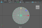
For the MASH Network, I needed to line the rocks up in the centre of the grid and I scaled each rock to be the same size. So that when the rocks are replicated in a straight line and look correct.


Ground
Following the development of the rock circle, I persisted with the rest of the modelling of the campfire. I modelled soil using a polygon plane to carve out a circle to go under the rocks. As a result, I selected an even number of faces leaving the one line of outside faces unselected therefore I circularized the faces to turn the square into a circle.


Subsequently, I deleted the outside faces just to leave the circle away from the rest of the shape. I resized the circle plane to be just a little bigger than the edge of the rock circle.


I selected the centre's 4 faces to give the centre a soft selection raise to give the centre of the circle plane a bump. I enhanced the bump by selecting the centre vertex to raise the centre more.


After finishing the base of the fire pit, I grouped the rocks and bumped the circle together to be one
object. I hid the campfire model to make it easier to see for modelling the next stage.
Wood Logs
Modelling
It follows that I commenced modelling a log for the fire that I could duplicate later with the same texture applied. I first created a cylinder polygon, which I rotated/resized to resemble a log before extruding each end.


I added 2 subdivisions to each cap of the cylinder, and I selected/deleted the centre faces to generate a
hole straight through the log. I scaled the hole using the vertex circle to make the hole bigger and
form a thinner outer edge.


I extruded the inner edges of the hole to produce more faces and a smaller hole that I could merge to centre (Edit Mesh>Merge to Center) to cap the hole.


I mirrored (Mesh>Mirror) the log on the Z-Axis in the Minus (-) Direction to make the polygon even
on both sides.


Now that’s the main body for the log done. It’s time to start extruding the edges of the log to give the detail more definition.

Most importantly now, I Delete All by History Type to the polygon so changes would disappear and not slow down the computer.

After modelling the main body of the log, I selected 5 faces to extrude out and I sculpted the corners and centre edges to make a rounded edge.


I replicate the same process for the other rounded edge and also the other side of the log (as seen in images).


When finishing the curved edges, I checked how the turbo smoothing would affect the overall look of the log.


After smoothing, I went through the model to adjust some values / properties to amend the shape for smoothing.


The log looked like this after a few alterations and turning turbo smoothing on.


After adjusting the ends of the log, I realised that the log needed to have the length modified.


So I also went to the other side of the log to alter those curves.


For a final time, I turned on the smoothing to see the last look of the log smoothed.


Following modelling the log's ends, I pulled at the vertex at the ends of the log to extend the length.


Once I completed resizing the log, I was required to add more topology lines between the extended sections. I used the multi-cut tool to add more edges to the model.


UV Mapping
When modelling was polished up, I commenced by correcting the UV shells for each part of the campfire.
The Ground plane:


The Rock Circle


I refined a few single rocks’ UV to perfect the UV Maps. I looked at the Cut/Sew tools to edit the UV Maps of certain rocks as a result of this, it helped me to check the compression & expansion in certain areas of the rock. Afterwards, I investigated the UV Mapping Create tab, looking into the Planar, Cylindrical, Normal-Based, Spherical, Camera-Based, and then finally looked at...


...the Automatic Map for this particular rock, next I had to Layout the UV shells. The layout feature
automatically repositions the shells consequently they don’t overlap the UV texture space and
maximises the spacing and fit between them. The layout ensures that the UV shells separate and
occupy their own UV texture space.


The final UV Map to fix was the log’s UV shells so I set them on Automatic to see how they would layout. But I didn’t like the layout hence I repositioned the log (in the camera view) and tried the Camera-Based, create layout.


Once using the Camera-Based layout, I used the Cut/Sew tool to cut seams to sew other seams together and finding the best layout of the shells I could.


Finally, I renamed the cylinder to Log and I combined the Rocks & ground geometry together to be one model.


I learnt to design a 3D campfire for this project for the reason of developing my skills in modelling in Maya and I needed a fire for the campsite that the puppets are going to experience.
I enjoyed modelling this campfire but creating the fire was stressful at first as I didn’t have a clear understanding of the Maya modelling techniques until Owen did a tutorial lecture on the subject. Before the lecture, I had to learn to model a campfire using a YouTube video which was hard to get my head around.
This campfire helped the project as it helped me to learn how to model a campfire structure from beginning to end accordingly to place into my campsite environment to develop the lighting system for the foreground of the scene.
I’m going to be learning to model a tent and foldable chair using an image plane as a reference afterwards I learnt how to develop this technique in a previous lecture.